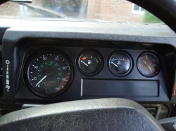
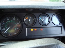
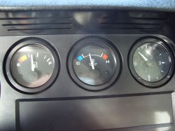
Installing a Defender Td5 Instrument Pack into a 200Tdi/300Tdi
 Category: Technical Articles
So, you want to be able to see your instruments at night?
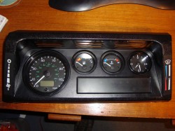
Firstly one needs to understand how the Td5 instrument packs differ from the older ones. The gauges are entirely electronic rather than the cable-driven speedo of days gone by, and the lighting also is much improved being properly backlit, to the extent of even the heater controls being lit. The conversion is reasonably easy, but does require a basic knowledge of wiring (how to crimp on non-insulated terminals properly etc.) to complete. Parts are not massively expensive, although of course it depends where you buy from. Gauges are always popping up on eBay now and then, as are the other instrument parts required, although the easiest way to do it is to just buy a complete Td5 instrument pack including the binnacle, all the gauges/dials, the warning light panel and the loom.
In order to perform this conversion you will need:
- A complete Td5 instrument pack (binnacle, speedometer, engine water temperature and fuel gauges, clock, and warning light panel. Usually available on eBay or at auto jumbles)
- Wiring loom for the above (YMG109280. Look on eBay or at auto jumbles)
- Td5 speedo transducer, about 15 feet of 3-core ~1mm2 cable and a 3-pin plug with pins (obtainable at Vehicle Wiring Products – product code ‘01252/3’)
- A ‘green’ 300Tdi temperature sender (AMR1425) & an adaptor if needed (see below)
- Two (get more though) extra pins for the speedo lower plug (obtainable at Vehicle Wiring Products – product code 3-7210)
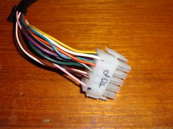
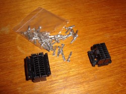
- A multi-plug connector pair (with terminals) of at least 11-ways. Some spare pins too
- Plugs and pins (and spares) for the warning light panel (RS part numbers below)
- A short (2 or 3 feet) length of 1mm2 thinwall cable, ideally in green/blue (GU)
- Some basic wiring tools and bits, crimpers, tape etc.
Part 1 – Fitting of Speedometer, Fuel and Temperature Gauges and Clock
The main involved part of this procedure is the adaptation of the Td5 water temperature gauge to the 200/300Tdi engine. In a standard Td5 the gauge receives its signal from the ECU, and so if you take the signal from the temperature sender in the thermostat housing directly to the gauge it will not read correctly, even with the correct (AMR1425) sender in there.
To get around this we make use of a handy feature put into the speedo by Land Rover (and VDO who made it). Because Land Rover kept producing 300Tdi-equipped vehicles up until a few years ago (ROW spec), but equipped them with the modern Td5 dash, there is a built-in way of making the 300Tdi temperature sender work with the Td5 gauge. This involves slightly re-routing the wires in the dash loom, hence the need for some extra pins in the lower speedo plug. For this guide, I will go through the steps required to achieve this second option.
It’s worth noting that you can actually buy a loom with this mod pre-done, it’s known as a ROW-spec dash loom (YMG109260) but they’re not cheap, if you can even find them.
The other option of course is to not bother with the Td5 temperature gauge at all, and instead fit an aftermarket one. The VDO Vision range is very popular, and matches the other Td5 gauges well. In this instance, you will not need the temperature gauge, 300Tdi sender, or extra speedo plug pins, and will not need to modify the loom as set out below, but instead need to obtain a matched aftermarket gauge and sender pair, as above. Bear in mind the sender thread, I believe the 200Tdi is a 5/8” UNF thread and the 300Tdi is 1/8” NPT.
Print out the diagram in the link below and keep it to hand. It shows the complete wiring layout for what you need to achieve gauge-wise:
Wiring Diagram – Td5 Gauges Installation into 200Tdi or 300Tdi Defender
As can been seen from the diagram above, most of the connections are to be made at the large multi-plug (which we will be replacing later on). The only work that needs doing within the loom is re-routing the temp sender feed to go via the speedo head before going to the gauge.
Okay, let’s get started. First task is to modify the Td5 loom.
The lower speedo plug, as referred to here, is the one with less wires on. It is the lower one on the back of the speedo if held in the correct orientation.
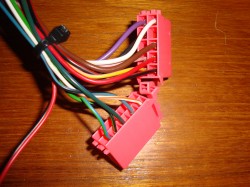
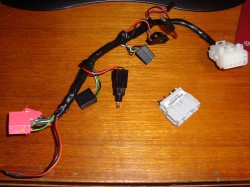
Open up your dash loom, now you need to take the Light Green/Blue wire that currently goes from pin 8 on the large multi-plug down to pin 2 on the temp gauge connector, and move the multi-plug end to pin 9 on the lower speedo plug (you can just cut the multi-plug end, as we’ll be changing it later). Cut the wire to the correct length, and then you will need to crimp on one of your new speedo plug pins. It should now go from pin 2 on the temp gauge connector to pin 9 on the speedo lower plug. This can be seen on the diagram, marked as Light Green/Blue (LGU). To add/remove pins to the pink speedo plugs, you will need to remove the yellow locking strip that should be visible from one end. Replace it once you have finished the modifications later on.
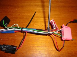
Light green/blue wire re-routed to lower speedo plug. The wire is not visible in the loom as it’s hidden inside (light green/black for fuel gauge is visible), but it can be seen emerging to the plug at the right hand end. Not yet terminated, as can be seen from the wire hanging out the end of the plug
Now take some new wire of the same gauge (ideally Green/Blue), and crimp on one end one of your new lower speedo plug pins. This wire then needs to run from pin 5 down to where pin 8 was on the multi-plug connector. Leave this un-connected for now as we will be changing this plug later.
To double-check, the feed for the temperature sender should come in on pin 8 of the multi-plug (or where pin 8 was) and then run up the loom into the lower speedo plug on pin 5. It should then exit this plug on pin 9, and run to the temperature gauge, where it enters on pin 2. Check yours against this and the diagram. Twice. And then again to be sure.
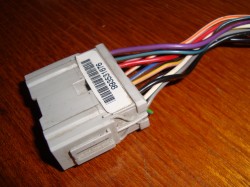
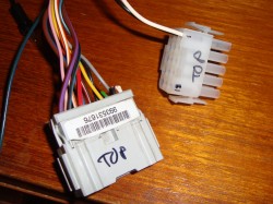
The next stage is to remove the grey multi-plug connector from the end of the loom and replace it with one half of the multi-way connector pair you bought. It will be easier to do this if you remove the loom tape (which you should have done anyway as above), and do the connections one at a time. That way you can make sure that the pin numbers stay correct and as per the diagram. Of course, as long as each wire matches up with its correct partner on the vehicle then it doesn’t really matter, but it makes diagnosis easier if you keep to the diagrams.
Now the loom modification is complete, the next job is to do some of the dirtier bits, in the engine bay and under the vehicle.
For the temperature sender you can re-use the existing wire, just fit the correct sender into the block. If you have a 300Tdi, then the correct sender (AMR1425) will fit straight in, however if you have a 200Tdi then you will need to purchase or make an adaptor to take the 5/8” UNF thread in the block down to the 1/8” NPT for the correct sender. This can be made by boring out the inner of your old 200Tdi sender and tapping it to 1/8” NPT, although I’ve not done it that way myself. I (lazily) bought an adaptor from http://www.europaspares.com/, although Vehicle Wiring Products also supply them as part of one of their ‘Brass Adaptor Kits’ (part number 52399).
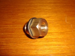
The 5/8″ UNF male to 1/8″ NPT female adaptor I’ll be using to fit the 300Tdi temperature sender to my 200Tdi engine
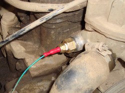
Now for the speedo transducer. You need to remove the old drive cable and its end fitting which will currently be residing in the nearside of the transfer box behind the parking brake’s back plate. Remove both and run your new 3-core wire in place of the old drive cable. On the end of this cable, attach the 3-pin plug as per the diagram, ensuring the wires are the correct way around. Fit the transducer in the hole (ensuring the drive is correctly aligned), and attach the 3-core cable as per the diagram. The other end (dash end) of the 3-core cable will need to be wired into an ignition switched live, ground, and the multi-plug when the time comes to it. Having a 3-core with different coloured wires is helpful here.
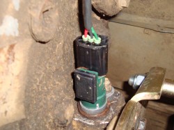
Transducer installed in side of transfer box. I used red for ignition switched live and green for the speedo signal, but as long as the pins match up on the diagrams the wire colours are irrelevant.
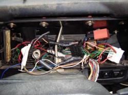
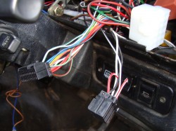
The third task is to wire in the second half of your multi-plug, remove your instrument binnacle (if you haven’t already done so) in order that you can get to the wires behind. Again, if you haven’t already then fit the new gauges to the binnacle now whilst it’s out.
What you have behind your instrument pack may well be individual to you, but you should be able to identify the wires of interest. You will need:
- One 12V ignition-switched feed (pin 1), this should be fused to 10A.
- Two permanent 12V feeds (pins 6 and 11), both fused to 5A each.
- Several earths (pins 2, 7 and 9), these can be combined to a decent earth point on the bulkhead behind the dash.
- Gauge lighting feed (pin 4, should be Red/Orange)
- Fuel tank sender wire (pin 5, should be Blue/Black)
- Water temperature sender wire (pin 8, should be Green/Blue)
- Speedo transducer wire (pin 10, you will have added this one)
The above needs to be wired into the other half of the new multi-plug, ready to attach to your newly modified dash loom. Make sure to check and double check that the wires all match up on both sides as per the diagram. You don’t want to put the wrong voltages down the wrong bits and ruin your new gauges.
The Td5 time clock just plugs into the loom on the plug designed for it. If you have a voltmeter or something else to go there instead then just leave this plug loose.
Once you are happy with the wiring, connect it up and give it a test. You will need to get the engine warm to test the water temperature gauge of course, but for the fuel gauge just check that it climbs to the same level that it did on the old one, and then keep an eye on it next time you fill up. The low-fuel light (if you have one) can stay connected straight from your sender, you don’t have to use the wire from the speedo for it. However, if you wish to then simply take the feed from pin 1 on the lower speedo plug to the relevant wire on the warning light panel. This is what I did, in conjunction with the new panel, as detailed below.
My last job was to alter the mileage reading on the speedo. In theory you could set it up on the bench with a power drill and wait…but I opted to take the speedo to Digidash, who changed the reading for me at a reasonable cost. I then fine-tuned with the drill to get it to the exact reading on the final day of fitting.
With any luck, you should now have a fully functional Td5 gauge setup. If for some reason you can’t get it to work then check and double check your wiring for errors or omissions. That said, the diagram I have drawn is what worked for me. Land Rovers being how they are, it’s not beyond reason that something could be different on yours, especially if it’s a foreign or different spec. vehicle.
Now, at this point you can leave the upgraded gauges fitted into your existing Tdi binnacle and be happy as larry, and I’ll note that it is worth doing this and just checking over a few days that everything works as it should, before doing the next part which is adding the Td5 binnacle and warning light panel.
Part 2 – Fitting of Td5 Instrument Binnacle and Warning Light Panel
First step here is to remove your old binnacle, undo the retaining screws, ensure everything is disconnected behind, and pull it clear. It’s very important here to label which warning light each wire came from when removing the wires from the warning light panel. This will make identifying them when wiring them into the new panel much easier.
Now the instrument warning light panel on the Td5 is LED-based rather than using filament bulbs, and it also has a smoked front so that the icons are only visible when lit. Cool stuff. In order to connect it to the existing vehicle loom we will need some plugs to go into the holes on the back:
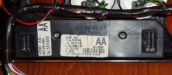
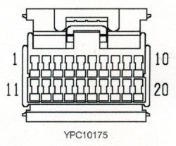
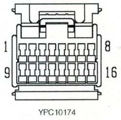
The back of the warning light panel, showing the plug apertures (16-way on the left and 20-way on the right)
The plugs can be obtained from RS Components either online or from a local trade counter. the part numbers are as follows:
- 20-way plug: 362-8796
- 16-way plug: 362-8780
- Terminals for both: 362-8869
The next and unfortunately quite arduous task is to wire the existing vehicle’s wiring into the Td5 warning light panel. Below are the pin-outs for the pins on the two plugs, showing what circuit each pin connects to. For most of the connections, it’s simply a case of wiring the existing wire from the vehicle into the correct pin on the correct plug. The indicator feeds can be run to the separate left and right icons rather than both terminating on the one symbol as per the pre-Td5 setup. There will be several unused lights in the panel, and you can use them for any purpose you like (a low coolant level sensor, winch power indicator etc.). To facilitate this, you will need to either connect the lamp to a 12v supply or an earth (switched via your device/sensor of course), depending on the lamp. In the table below it shows which require an earth to illuminate and which require a 12v supply.
Large Plug (20 pin) |
|||
| Cav |
Colour | Circuit | Polarity |
| 1 | Blue/White | Main Beam | Live + |
| 2 | Green/White | Right Indicator | Live + |
| 3 | White/Orange | Low Fuel | Earth – |
| 4 | Red/Yellow | Rear Fog Light | Live + |
| 5 | Orange | Engine Immobilised | Earth – |
| 6 | Black/Pink | 120km/h Over-speed Warning (Gulf States Only) | Earth – |
| 7 | Black/Blue | Diff-lock Engaged | Earth – |
| 8 | White/Black | Rear Heated Screen | Live + |
| 9 | Black/Red | Hazard Warning Light | Live + |
| 10 | Light Green/Purple | Trailer Warning Light | Live + |
| 11 | Red/Slate | Engine Management Light | Earth – |
| 12 | Black/Yellow | Glow Plugs (Diesel Models) | Earth – |
| 13 | White/Brown | Oil Pressure Warning Light | Earth – |
| 16 | White/Green | Ignition-switched Live Supply for Panel | N/A |
| 17 | Yellow/Brown | Charge Warning Light | Earth – |
| 18 | Green/Red | Left Indicator | Live + |
| 20 | Red/Orange | Side Lights | Live + |
Small Plug (16 pin) |
|||
| Cav | Colour | Circuit | Polarity |
| 1 | White/Green | Ignition-switched Live Supply for Panel | N/A |
| 2 | Yellow/Black | Cold Start (Petrol Models) | Earth – |
| 4 | Orange/Green | Water-In-Fuel Warning | Earth – |
| 5 | Slate/Red | Transmission Oil Temp Warning | Earth – |
| 6 | Red/Slate | Connect to pin 10 | N/A |
| 7 | Red/Slate | ABS Light | Earth – |
| 8 | Black | Earth for Panel | N/A |
| 9 | Black/White | Connect to pin 13 | N/A |
| 10 | Red/Slate | Connect to pin 6 | N/A |
| 13 | Black/White | Connect to pin 9 | N/A |
| 14 | Black/White | Brake Low Fluid/Handbrake Warning | Earth – |
| 16 | Yellow/Slate | Traction Control | Earth – |
As can be seen above and in the wiring table you have to link some of the pins across onto one another on the smaller plug. This is a workaround for non-ABS vehicles and stops the light being on all the time.
Plug the multi-plugs into the back of the warning light panel, and refit your dash. You should now be able to give all the circuits a good test, checking that everything still works as it did beforehand. That should be it!
Disclaimer, Summary & Thanks
Okay, so now with any luck your gauges and warning light panel should all be fully functional. If you have any problems, the obvious thing to do is check your wiring again against this information, however the information posted here is what worked for me and what I have heard worked for others…due to Land Rover’s unique ability to mix-and-match vehicle parts it is by no means guaranteed to work for you. For example, the colours didn’t quite match the diagrams in my vehicle, I think because of silly previous owners. That said, there is always a way around the problem.
I want to thank the good people over at the LR4x4 forums, special mentions go to Mo Murphy, Western and Diesel Jim as these guys are the ones who initially dug out all the information above, all I’ve done is collate it together, make up some diagrams and write the guide. If you do have any issues with this conversion, the forums are the place to ask.
Regards
