Auxillary Fusebox Install
 Category: Technical Articles
For reference purposes, here’s my Defender auxillary fusebox install. We begin in the battery box:
The supply wires to the fusebox are 16mm², rated for 100 amps. As such, there is an in-line 100 amp fuse mounted to the side of the battery box. This keeps the supply safe as it is fused right next to the battery and before any routing through panels.
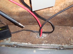
The two large gauge wires described above exit the back face of the battery box through a grommet, and then head upwards through the seatbox top through a second grommet-filled hole:
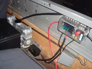
This takes us to the main bulk of the system. Mounted on the bulkhead behind the passenger seat we have:
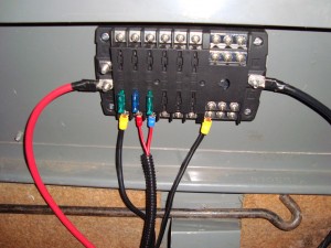
The fuxebox itself is a reasonably expensive unit (£30 odd from VWP), but it features up to 12 fused circuits in two seperate banks of 6. I’m only using the bottom bank in mine for now. Each circuit is rated for 30 amps and each bank for 100 amps (hence the supply cable/fuse ratings). It also provides 12 common earths as well, although I imagine these are of less use for most remotely positioned accessories.
As it stands I only have three circuits wired in, the 12V compressor, the central locking system, and the engine cooling fan circuit:


